Does this look complicated? Don’t worry … upgrading your Behmor 1600+ Control Panel is easier than you think!
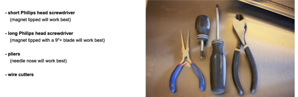
What you will need:
2 screwdrivers, pliers and wire cutters
Connecting the Control Panel:
Before you do anything, make sure your BehmorA popular electric drum roaster designed for home use, with variable batch sizes (from 1/4 pound to 1 pound) and a smoke-reduction system. It has been modified and... ...more is unplugged. You will be removing the side and top panels by removing 26 screws. 21 screws will be the same size (some silver, others black), and 5 are smaller. We recommend placing the screws for that panel inside its open cavity to help you stay organized. Before you start, unplug your machine…and we’ll say it again for the third time, unplug your machine. Please. Thank you.
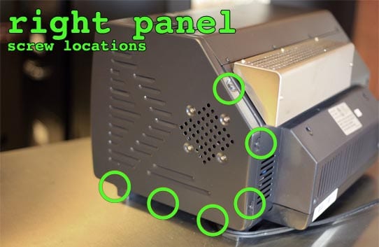
1. Remove the right panel – 6 screws.
Three screws under the panel lip, three on the angle and back. Once removed slide from back to front. The fan is attached so remove slowly, then disconnect DC power wire from PCB (printed control board).
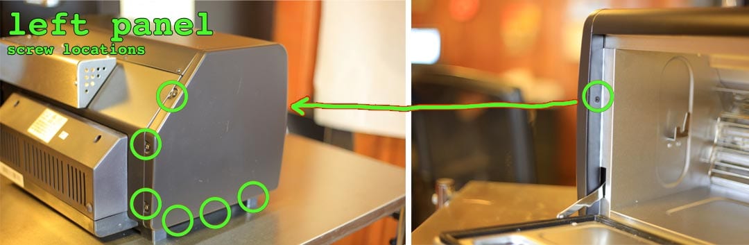
2. Remove the left panel – 7 screws
Same as right side but with an additional screw inside by the chamber door. To locate, open the chamber door and look inside the door opening. The screw just inside the door is smaller than the rest. Once removed slide the panel from back to front.

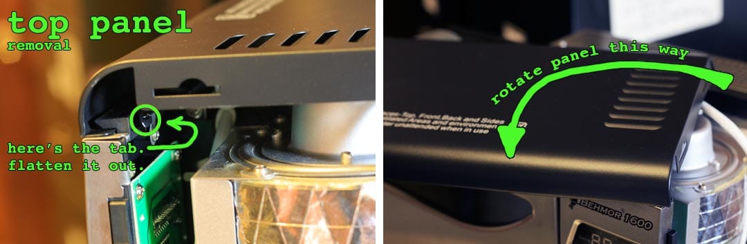
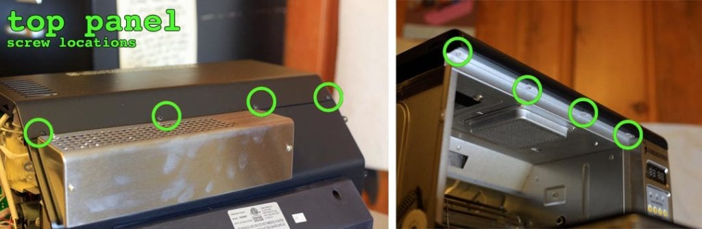
3. Remove the top panel – 8 screws
Four screws are located under the lip of the door opening (these are smaller than others). Four screws are located along the top back.
To remove the top panel you must first straighten a T-shaped tab (see photo) so it slides through a guide. The “T” is located inside the top right side of the roaster, just above the control panel. Straighten the “T” with a set of pliers until it is flat and horizontal. This will enable the tab to slide through the guide. Rotate the top panel, so the left side swings forward, then slide the right side free from the guide. Note that you will be doing this in reverse during reassembly.

4. Remove the control panel – 5 screws
Take note of the the gap between door and panel. You will need to refer to this later. Start with the three screws along the side of the roaster, then remove the bottom two screws. Lay the panel flat. If there is glue, the panel can still be easily dislodged/removed. Use your wire cutters to clip the zip tie and disconnect the cable and wire. Take note of the pin on the door and the groove on the front panel’s side. When replacing the panel you will need to make sure the pin slides into the groove.

5. Putting the Behmor back together again
Plug in the control panel’s two connectors and replace the top screw. Check the bottom area by the pin, then look upwards. Is the gap similar in spacing as before? If not, remove this screw and redo. Plug in the roaster and test the PCB: Press each button within each group in the following order: Press all weight buttons starting with ¼, ½, to 1 checking that the time in the display changes. Next, make sure the display changes when pressing P1 through P5. Press A through D, again noting display changes. Press “+” then “-“, light, cool, then lastly OFF. Start will be tested in the next step. Failure to follow the order as indicated, may lead to the false impression that buttons C and D are not functioning. These buttons are designed to not function in certain instances as discussed in Part V Paragraph 6 of the manual
System test: Unplug the roaster- while holding/pressing Start- plug in your roaster then release Start. You should see a series of numbers and hear components (fans) and lights come on- This should cycle fully twice- Note 120 should appear early in the self test. Unplug the roaster. Did everything test OK? If not, recheck your two connections. Make sure everything is properly re-inserted. Plug in the roaster and retry. If you are without a display, unplug the roaster and contact Behmor at [email protected]. If everything tested OK, re-insert and tighten all the screws.
Top panel: With the panel horizontal, gently insert the “T” through the guide and swing it around so that it lays flat on the top of the roaster. Check of the area on top of the control panel to insure is it flat. Bend the “T” so the panel is locked into place. With the top panel in position, open the roasters door and re-insert the four small screws under the lip. Do not tighten any screw all the way until all are in part way. The first screw should be top left, then top right, finally the middle two. Once they are part seated tighten them all in the same order. Doing this will insure the panel is properly aligned for each screw.
Next, re-insert and tighten the top panel’s back four screws, far left, far right then the middle areas.
Lastly, replace the two side panels. Left panel first (remember the small screw inside), then right side panel. Make sure in each instance you have all of the front and side guides going into their respective holes/openings.
To see the larger image sizes of the above photos, click on them in this gallery view!

What you will need 
Right panel screw locations Behmor left panel screw locations Top panel screw locations Removing the top panel Control panel screw locations